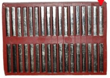
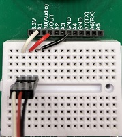
Initial Setup

  1. Secure your servo, one of the servo horns (your choice which one to use), and a 3 pin double sided header.
    Servo Servo horns Doublesided headers
  2. If needed, plug the servo into a 3 pin double sided header (image on the right). Doublesided headers
  3. If it is not already attached to the servo, select one of the servo horns from the plastic bag and gently press it on to the servo shaft.
    Servo Horns Servo without horns Servo with horn
  4. Connect wire jumpers from your header (the component you soldered onto your PCB) to your breadboard as shown in the table and image below. Mouse over the table below to highlight the connections. Then plug in the 3 pin header connected to the servo to the breadboard, directly beneath where the jumper wires are connected (ensure the servo is oriented correctly). Note: you do not need to use the particular colors shown for each wire. Also, note that the image shows shortened wires for clarity - your wires are longer.
    Servo Cable Color Header Socket Label
    brown or black GND
    red VOUT
    orange, yellow, white, or blue A1
    Wiring

Servo Calibration

  1. Copy the code below to your device and run it.
  2. The servo should now be alternating between spinning full-speed clockwise, stopping, spinning full-speed counterclockwise, and stopping, as indicated by text in the Mu console and on the Gizmo display. If the servo doesn't move at all, check the troubleshooting step 5. If the servo is spinning when it is supposed to be stopped, use a small Phillips screwdriver to turn the potentiometer on the underside of the servo (looks like a tiny screw head) gently in a clockwise direction. If the servo speeds up, turn the potentiometer in the other direction until the spinning stops.

    Wiring Wiring

    Once the servo stops and turns in concert with the text in the Mu console display and Gizmo display, the servo is calibrated.

Make a Robot! (GRADED)

  1. This program below turns your device into a robot because it performs the “sense-think-act” cycle that all robots do by reading the temperature sensor (sense), calculating how fast to spin the servo based on that temperature (think), and then sending a signal to the servo motor to make it spin at an appropriate speed (act).

    Copy the code below to your device and run it by clicking the "Save" button. The motor will be off or spinning slowly at low temperatures (such as ambient room temperature) and will spin rapidly at higher temperatures (like when you touch the temperature sensor with a finger and heat it up).

  2. It is your job to trace the remaining above program and identify what lines represent the SENSING, THINKING, and ACTING for this robot.

    Note: Your temperature and RPM may vary from the image below depending on the room temperature.

    Temperature Sensor Robot
  3. After you review the program and locate the relevant lines, you must explain to your instructor which parts of the code perform the Sense, Think, and Act steps. Be specific by referencing the line numbers. This explanation is required and is part of your grade!

Robot Activities (GRADED)

You will be graded on your successful completion of the activities below. Starter code is provided; however, it is necessary to modify the code to complete the task. Use your experience with Python programming concepts (iteration, conditionals, order of operations, functions, etc.) and the previous examples to complete each task.
Robot Activities
  • Activity 5:
    Create a button-activated propeller! Write a program that spins the servo counterclockwise while button B is held down and clockwise while button A is held down. If neither button is pushed, the servo shouldn't rotate. You choose the speed.
  • Activity 6:
    Create a light-activated fan! Write a program that will adjust the servo's speed based on input from the light sensor. The brighter it is, the faster the servo should spin.
  • Activity 7:
    Create a tilt-activated motor with NeoPixel light tilt indicators! Write a program that continuously adjusts the servo's speed based on input from the accelerometer. If the device is tipped to the left, the servo should spin counterclockwise. If it's tipped to the right, the servo should spin clockwise. The more it's tipped, the faster the servo should spin.

    Additionally, use the NeoPixel lights to visually indicate the direction of the tilt.
    • If the device is tilted to the right, the right half of the NeoPixels should light up green.
    • If the device is tilted to the left, the left half of the NeoPixels should light up green.
    This provides both motion and visual feedback based on the tilt of the device!

Verify this with your instructor. This is part of your grade! You must complete all the robot activities before the end of Lab 3.

When complete with all in class activities, you can move onto the GenAI Activity.